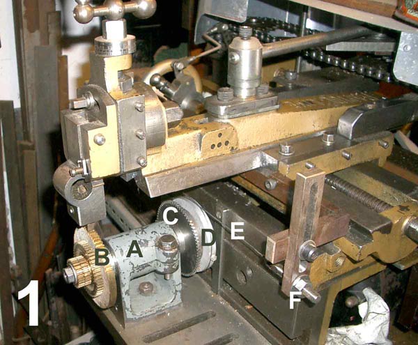
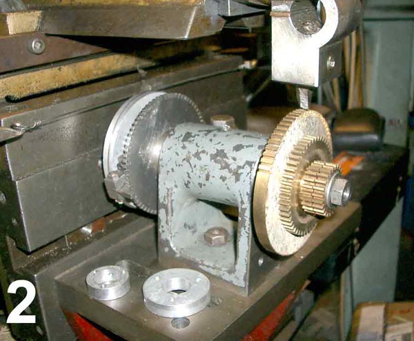
Image No. 1 showing the setup with A being the work head, B the blank to be cut, C a division wheel with the correct divisions to enable the required number of teeth to be indexed, D a pitch circle disc for the gear to be cut, E tension wire anchored to the tensioning screws and bracket F which is attached to the carriage.
With the shaper in motion, as the carriage is moved by the auto feed, the blank is turned by the piano wire around the pitch circle disc, thus generating the correct involute gear form with a single point tool ground to the form of a rack tooth for the diametrical pitch of the gear to be cut (This tool will, of course, be suitable for gears of any number of teeth for this DP). After one tooth is cut, the carriage is returned to the start position, the blank indexed one tooth and the next tooth cut and so on. The curved sides of the tooth being made up from a series of small flats, the finer the feed, the smaller the flats. Several blanks for the same size gears can be cut at the same time (the odd size blanks shown here on the work head are just for packing)
| Home | Back to Workshop | Links |